Test improvement updates
In order to ensure that we can always provide the high-quality products(cables, wires, wire harness, and cable assembly), we have high requirements for quality testing, So we need a comprehensive quality inspection management system, We need to test from raw materials, production processes and to the finished products, We also need to constantly update and improve our testing equipment, and we must periodically verify the testing equipment. YCABLE ELECTRONICS always approach from the customer's perspective, constantly improving ourselves, update the test improvements to ensure that every product can meet customer requirements.
Quote NowTest improvement update
HD 10 series, male and female 6 pin and 9 pins
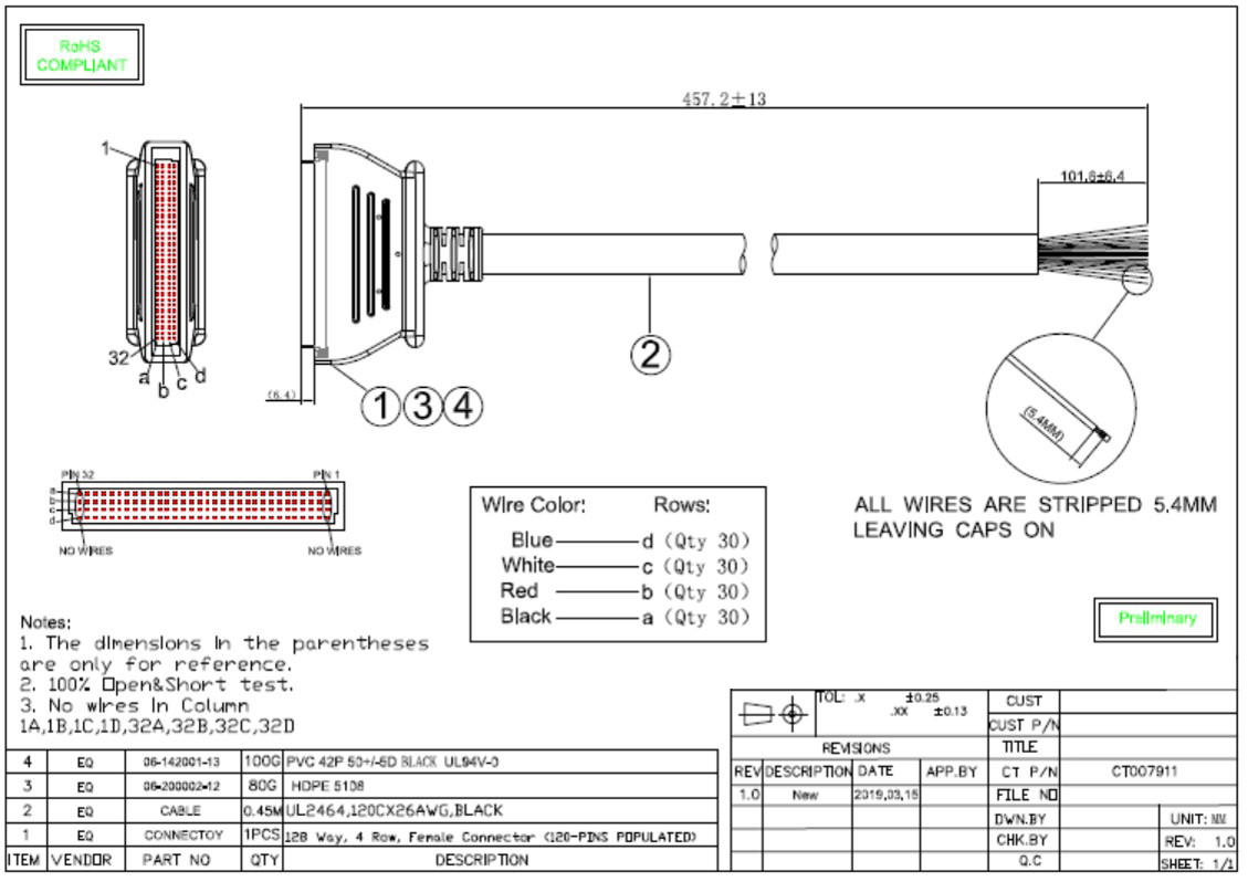
3-1 Case Study Molded cable assembly with 128 flying wires
3-1.1. Drawing
3-1 Case Study Molded cable assembly with 128 flying wires
3-1.2. Failure Mode
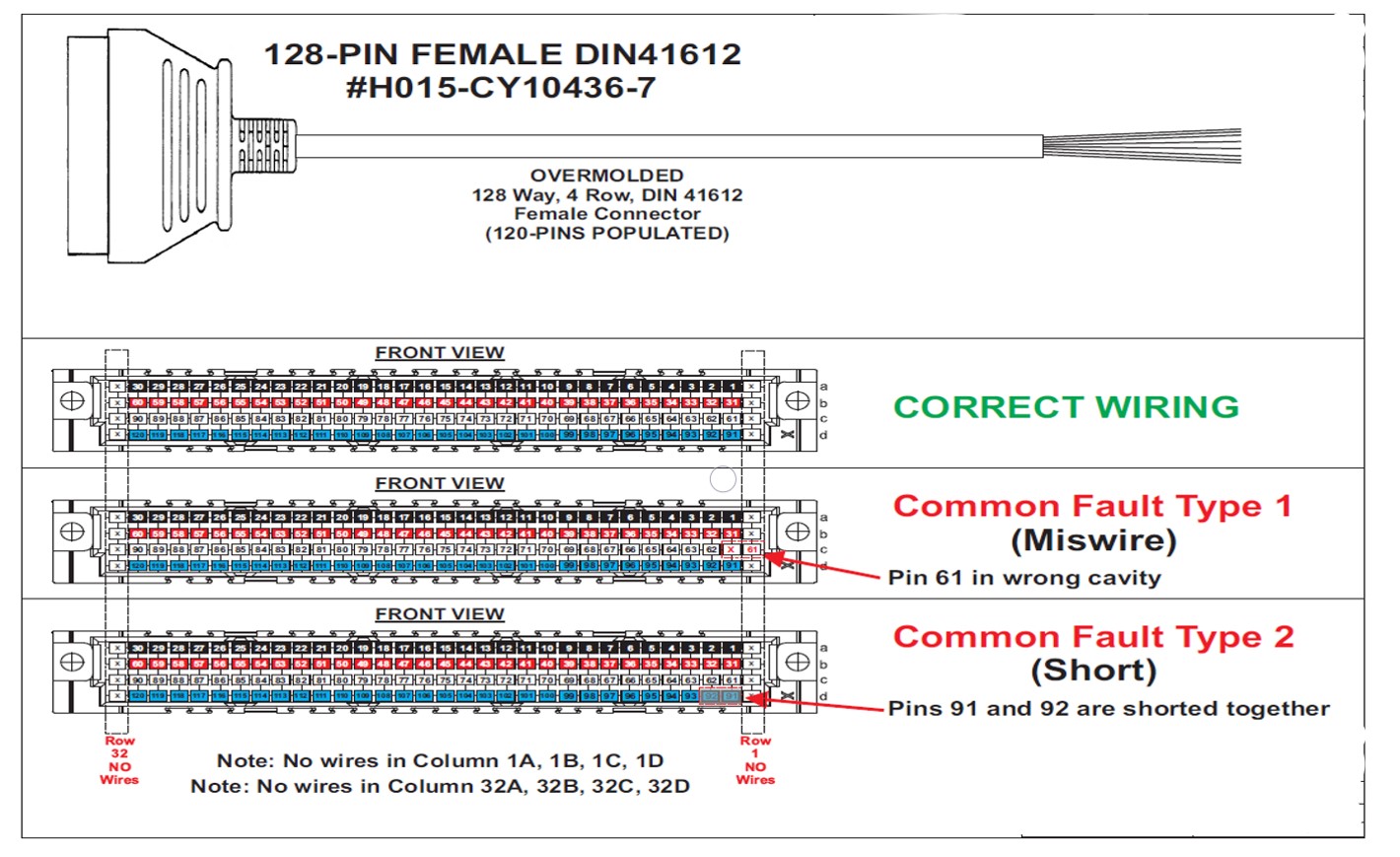
3-1 Case Study Molded cable assembly with 128 flying wires
3-1.3. Test Process-1 (before cutting)
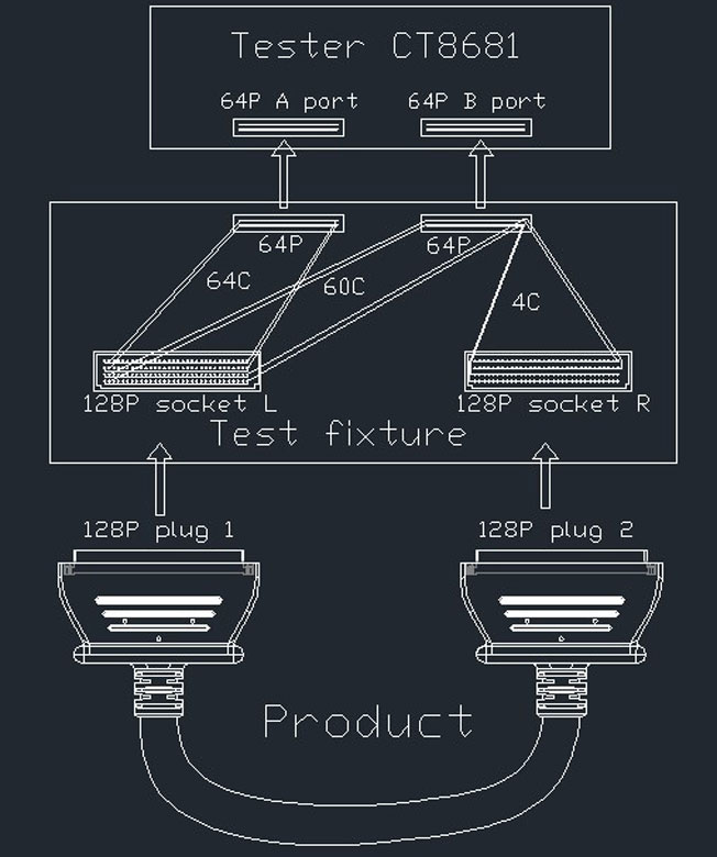
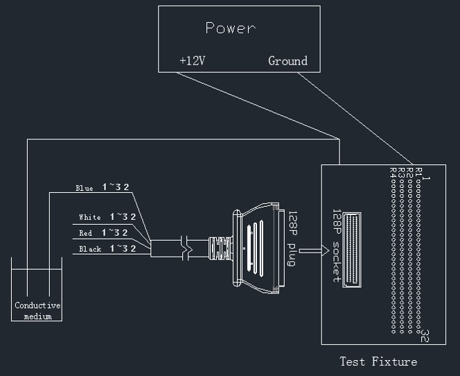
a) Block Diagram
b) Fixture Construction and Setting
c) Test Procedure
d) Test Result for Open, Miswire, Short
e) Screen Shot on Analyzer
a) Block Diagram
b) Fixture Construction and Setting
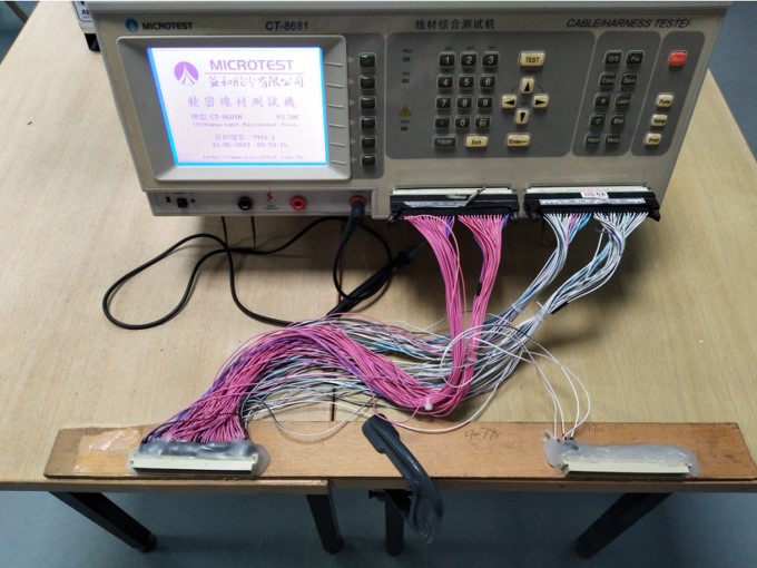
3-1.3. Test Process-1 (before cutting)
Socket L Setup-
1.here are 4 rows on 128P socket L. One disabled column on both ends of socket L
are shorted together on each row
total 4 shorted-pins on socket L:
row a (2 ends shorted)
row b (2 ends shorted)
row c (2 ends shorted)
row d (2 ends shorted)
2.There are 30 columns on 4 rows in the middle of socket, plus 4
shorted-pins, total 124 pins are deployed as test points on the socket L of the
fixture.
3.Connecting Socket L to CT 8681 Analyzer- socket L setup completed
Socket R Setup-
1.There are 4 rows on 128P socket R. Each 32 pins on each rows are shorted as 4
shorted-wires on 4 rows each.
2.Connecting socket R to CT 8681 analyzer- socket R setup completed
c) Test Procedure
3-1.3. Test Process-1 (before cutting)
Analyzer Calibration before Test-
1.Complete test fixture setup according to block diagram then start up the Analyzer
2.Connecting the analyzer with master sample every time before continuous testing
3.Calibrating the analyzer and setting with master sample to standardized parameters
4.Remove master samples and ready for testing activities – calibration completed
Testing Steps-
1.Plug-in tested product to socket L/ R to the fixture (P1-socket L/ P2-socket R)
2.Test open/ disposition via analyzer
3.Test short via analyzer
4.Reverse the P1/P2 of tested product to fixture (P2-socket L/ P1-socket R)
5.If the analyzer shows fail, separate the failed product off the production
d) Testing result for Open, Miswire, Short
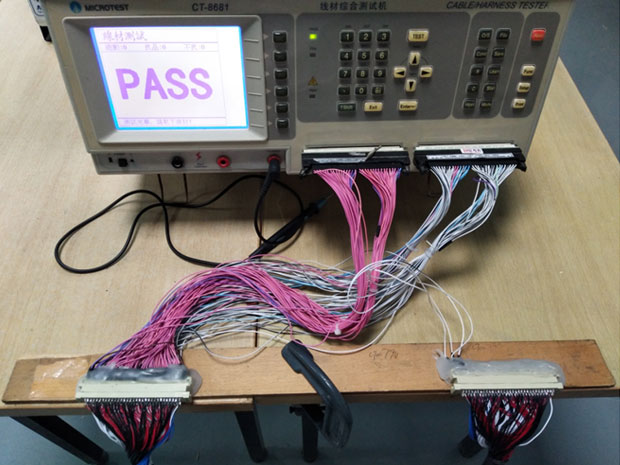
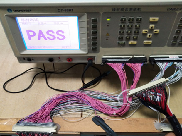
e) Screen-Shot on Analyzer
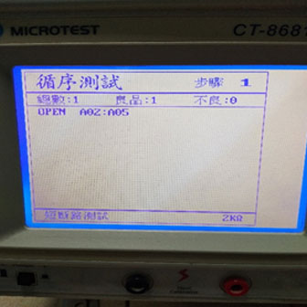
Test Open
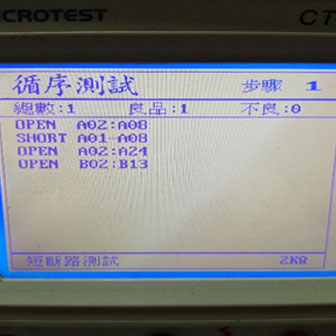
Test Open/ Short
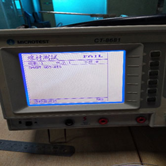
Test Short

Test Open/ Short
3-1.4. Test Process – 2 (after cutting)
a).Test Block for trouble shooting
b).Test Fixture for Miswire Test
c).Test Procedure
d).Conclusion
a) Test Block Diagram for Trouble Shooting
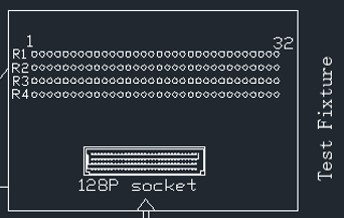
b) Test Fixture for Miswire Test
3-1.4. Test Process – 2 (after cutting)
LED Color Designation
a).Test Block for trouble shooting
b).Test Fixture for Miswire Test
c).Test Procedure
d).Conclusion
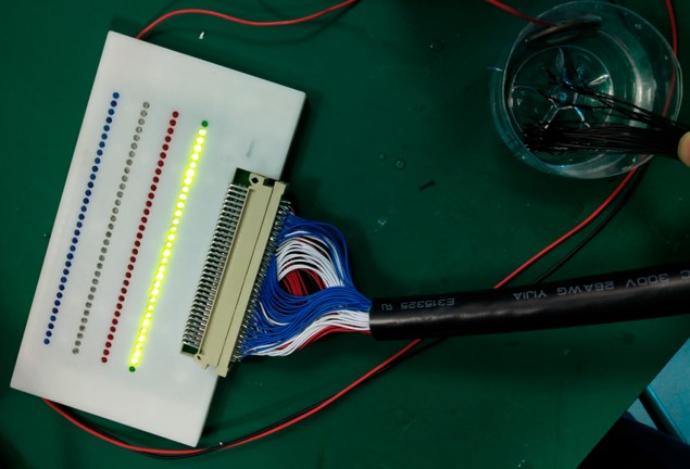
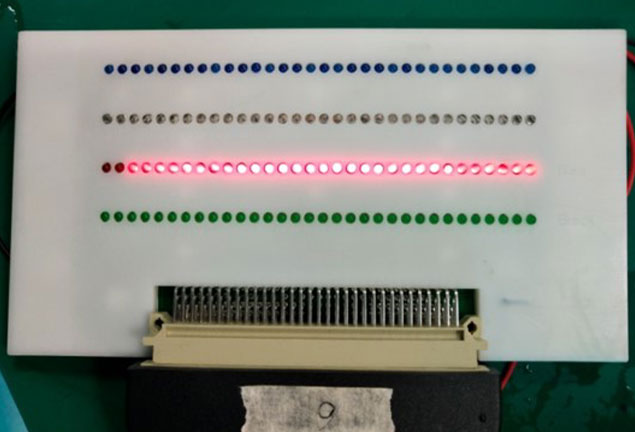
c) Test Procedure
3-1.4. Test Process – 2 (after cutting)
1).Connect the fixture board to the 12v power supply
2).Connect the product to fixture, put all blue wires into the water.
3).Then the 30PCS green LEDs of the first row should be lightened
4).Put all white wires into the water.
5).Then the 30PCS red LEDs of the second row should be
6).Put all red wires into the water.
7).Then the 30PCS green LEDs of the third row should be lightened
8).One red LED lighten shows miswired-position on pin#119
9).Put all black wires into the water.
10).Then the 30PCS red LEDs of the fourth row should be lightened
11).Go and No go indication: If there is any miswire occurred, the LEDs will show the abnormal position on the LED board of fixture.
d) Conclusion
• Empower the production line to sorting out defectives, if occurred.Capable to accurately detecting the suspicious wire position
• Availability of full test procedures had been proven 100% viable
• 100% test result accuracy before and after cutting
• Guaranteed 0% defective shipping to customer
3-2. Case Study
Molded cable assembly, HD 26 to OBD II, durability test
General guideline: Temperature extremes are -10c and 80c. Cable shall be placed at each extreme temperature for at least 2 hours prior to testing. No physical breaks in the cable jacket, conductors, shielding as well as any applicable overmolding material shall occur. All functionality shall remain intact.
Test methods:
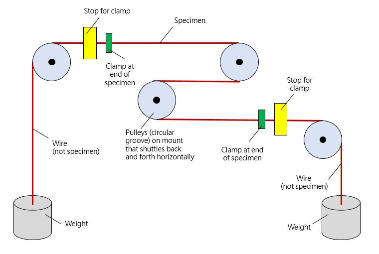
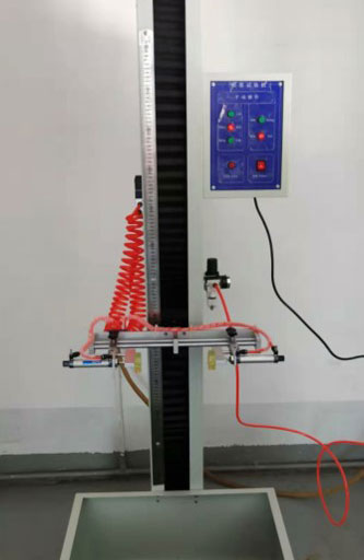
3-2.1. Pull Test
3-2.2. Bend Test
3-2.3. Torsion Test
3-2.4. Drop test
3-2.1. Pull Test
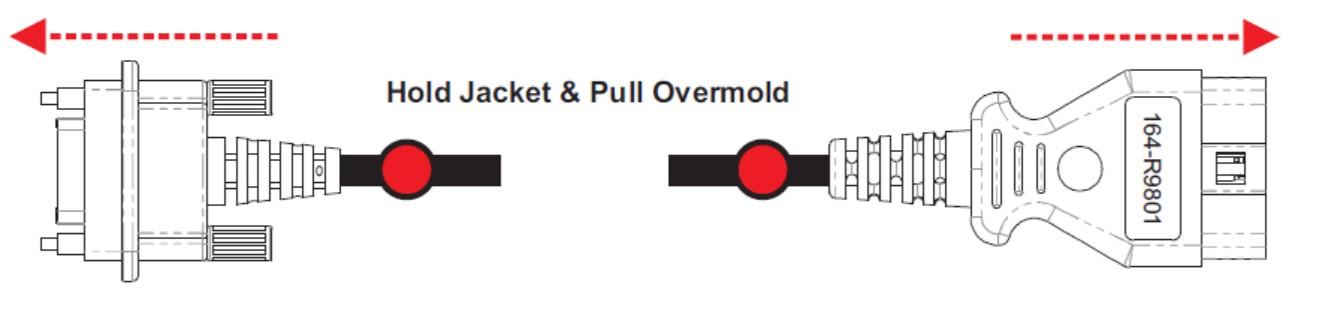
Pull force: 40N for 10 seconds
Test times:25 times
3-2.2. Bend Test
Test 1: Conditions and Method
Bend at center of cable jacket, at a radius of 5x the o.d. of the cable jacket, in 10 seconds intervals, at each temperature extreme -10 and + 80. Cable jacket shall remain intact protecting individual conductors
Test 2: Conditions and Method
With 5 pounds of weight added to the opposite end, bend at the strain relief base of both molded ends, at a radius of 5x the o.d. of the cable jacket, in 10 seconds intervals each, at each temperature extreme at -10 and + 80. . Cable jacket shall remain intact, as should the mold material, protecting individual conductors and maintaining strain relief properties
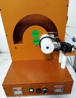
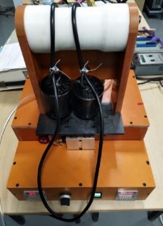
3-2.3. Torsion Test
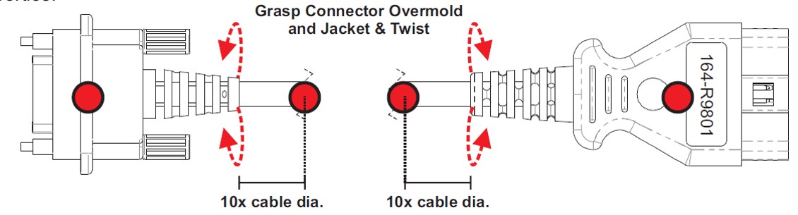
Test conditions and method
• Grasp the connector overmold and the cable jacket at a distance of 10X the cable outer diameter and twist cable at the strain relief base of both molded ends to approximately 180 degree turn, with 20nM pull forced applied, at 10 second intervals, at each temperature extreme. Cable jacket shall remain intact, as should the mold material, protecting individual conductors and maintaining strain relief properties. • test cycle times: 2500
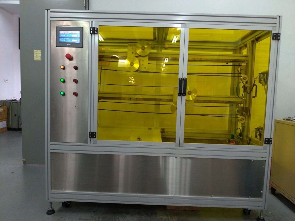
3-2.4. Drop Test
Test equipment
Drop cable assembly from 4 feet at temperature extremes.
Perform this test 25 times. Mold material shall remain intact, protecting individual conductors and maintaining strain relief properties.
Test conditions and method
Height: 4 feet
Test cycle: 25 times per each extreme temperature requirement
Testing evaluation standard
Cable jacket shall remain intact protecting individual conductors and maintaining strain relief properties
Electrical test pass
3-2.5. Conclusion
All demonstrated test programs are defined by customer. Cabletree ensures all tests are aligned with requirements proceeded in house.
Cabletree shall retain humble execution as our tradition, to secure customers' satisfaction and requirements.
We care what our customers' mostly care:
• Quality
• Engineering Communication & Solution
• Cost
• On-time Delivery
3-3 High Flexible Control cable Compliance test
High Flex Control Cable TEST SETUP